 Is specialized in the transformer \ regulator \ regulator \ wire and cable and all kinds of high and low voltage power supply development, development, production and marketing of high-tech company, seated in the Jiading High-tech Development Industrial Park, a beautiful environment and convenient transportation.
 The company passed the ISO9001 quality system certification, in the spirit of science and technology is the highest, quality is the.
 Company products are exported to all over the world.
 Company's products are sold throughout the country, the establishment of the vast number of sales network and after-sales team.
 In order to protect the after-sales service, return customers to our consistent trust and support.
 The introduction of more high-quality products to return the vast number of customers.
 Mobile phone��15021754889
PRODUCTS
PRODUCTS
|
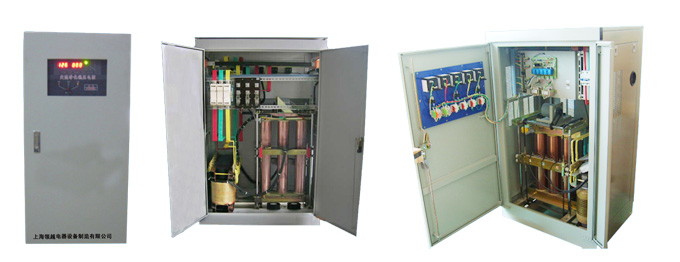
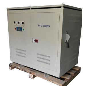
SBW three phase power regulator automatic voltage regulator, compared with other types of large capacity, high efficiency, no waveform distortion, stable voltage regulation. Overcome the high-power inductive load on the grid shocks caused by unstable voltage power grid to meet the load-wide, can withstand transient overload, long-term continuous operation, manual control switch freely controlled, with overvoltage, undervoltage, phase sequence , lack of equal protection device automatically, other features automatic power, delay output, the output back to the middle, easy installation, reliability and other characteristics.
Specifications and characteristics
• Input voltage range: 380V �� 20% (304V-456V) • Output voltage precision: 380V �� 1 ~ 5% adjustable (can withstand the instantaneous current 5 times) • Frequency: 50Hz-60Hz • Withstand Voltage: 2000V 1 minute without breakdown • Efficiency:> 98% • Waveform Distortion: Nil • response time: �� 1.2s • Insulation class: F class 155 �� • Insulation resistance: �� 2M�� • Features: True RMS with a clean sample electronic board (for frequency, capacitance compensation arising from the work of the magnetic field, electromagnetic waves and harmonic interference and the suppression effect of the output voltage fluctuation). Work SBW series regulator compensation from the three-phase transformer TB, TUV-phase voltage transformer voltage detection unit, servo motor control and drive mechanism, contactors operating circuit, protection circuit. The gas block diagram shown in Fig. TUV voltage transformer winding connected in a Y-shaped, connected to the regulator output, the secondary winding with a winding compensation transformer TB, while the compensation transformer secondary winding in series in the main circuit. A phase is the column, indicating that the regulator works, shown in Fig. Excluding the compensation transformer impedance voltage drop, can be seen from Figure II: Regulator from the voltage regulator circuit, the voltage detection circuit, servo system and control circuit, whose electrical wiring diagram of the principle as follows: 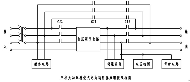 Voltage regulator circuit is composed of contact voltage regulator component B and C compensation transformer. Contact voltage input connected to the regulator output, the output transformer in series in a coil of compensation, the compensation transformers secondary coil is in series in the main circuit.
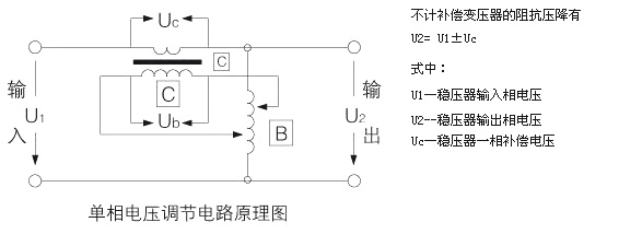 When the input phase voltage change �� U1 U1, if the compensation voltage Uc corresponding changes �� Uc, and �� U1 = �� Uc, the output phase voltage U2 can be maintained, the compensation voltage Uc of the changes under exposure to the output voltage regulator to change. Contact regulator by electronic logic control circuit changes according to the output voltage automatically changes the output voltage. UA0 = UAI + UAC Where: UAI --- A-phase input voltage regulator; UA0 --- A-phase output voltage regulator; UAC --- A phase compensation voltage regulator; The principle is: When the A-phase input voltage UAI increased ��UAI, the compensation voltage UAC also changed accordingly ��UAC, and UAC =- UAI, the A-phase output voltage UA0 unchanged Similarly phase B, C phase also do so. The regulation process is: According to the output voltage changes, voltage detection unit by the sampling, detection and control servo motor output signal SM rotation, driven by the gear box by a chain of brush on the voltage regulating transformer set TUV slide (or roll) to voltage transformer secondary voltage regulator to change the polarity and size of the offset voltage to achieve stability in automatic voltage regulator output voltage setting accuracy to the extent permitted, so as to achieve the purpose of automatic voltage regulator. |